Once you understand the overall jig design workflow, it’s time to actually open up CATIA and start modeling.
“Isn’t CATIA that complex software used for aircraft surface design? Sounds intimidating.”
CATIA is well known for its GSD (Generative Shape Design) workbench used for complex aerospace and automotive surface work. But the jigs we design are mechanical parts — blocks of steel that are milled and drilled. That means instead of advanced surface commands, the Solid modeling tools in the Part Design workbench are what you’ll use every single day.
In this post, we cover the 5 most essential CATIA features you’ll click hundreds of times a day on the job — fully explained with real-world tips.
1. Pad — Extruding a Sketch into a 3D Solid
- What it does: Takes a 2D sketch profile and extrudes it perpendicular to the sketch plane, creating a 3D solid body.
- Pro Tip: Pad is the very first command you’ll reach for when building a jig base plate or any bracket frame. Always fully constrain your sketch relative to the Origin — unconstrained sketches cause catastrophic model rebuilds when you need to make edits later.
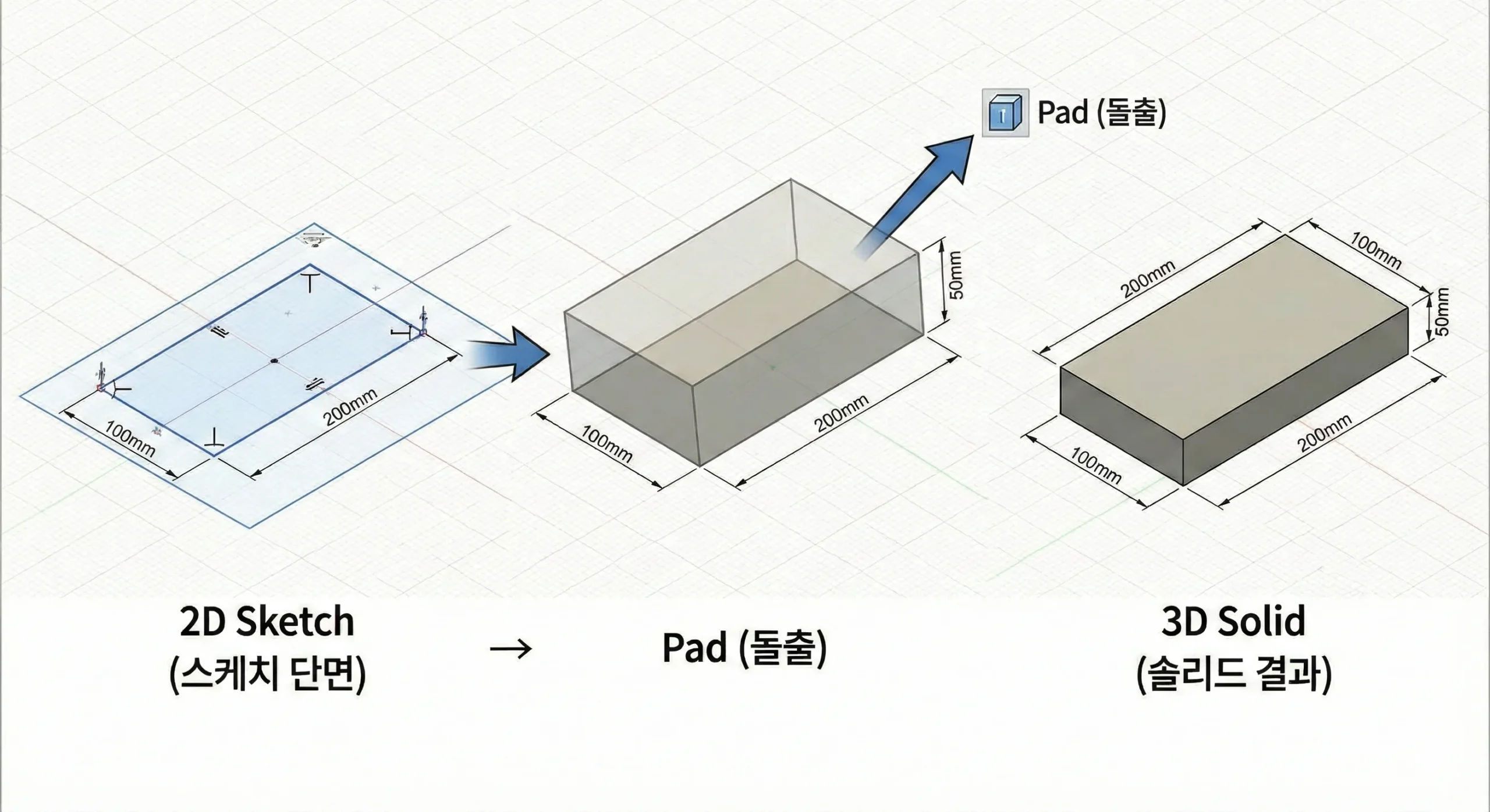
▲ The most fundamental CATIA command — ‘Pad’ converts a 2D sketch into a 3D solid body
2. Pocket — Cutting Material from a Solid
- What it does: The opposite of Pad — it removes material from an existing solid according to the shape of a sketch, creating recesses or through-cuts.
- Pro Tip: Pocket is used to carve out clearance spaces so that components don’t collide (e.g., around locators or clamp brackets), or to lighten a heavy steel block by removing unnecessary volume.
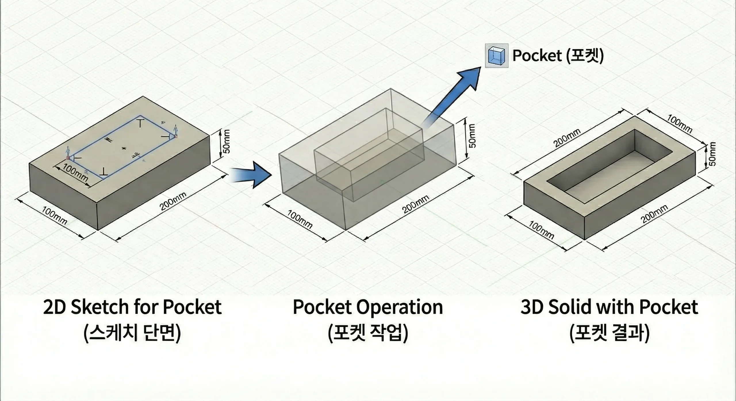
▲ ‘Pocket’ removes unwanted material from an existing 3D solid
3. Hole — Precision Fastening Starts Here
- What it does: Creates machining-standard holes for bolts to pass through, tapped threads, or locating pins — with proper engineering specifications built in.
- Pro Tip: Beginners often sketch a circle and use Pocket to make a hole. If you’re planning to create 2D drawings, always use the Hole feature instead. It lets you define tap thread specs like M8 or M10, and when converting to AutoCAD 2D, the hole’s center mark cross lines are automatically recognized.
- The Hole feature lets you embed tap thread specifications like M8 or M10 directly into the model.
- When exporting to AutoCAD for 2D drawings, center mark lines are automatically recognized, saving significant time on drafting.
- A Pocket-based circle is just empty space — it carries no standard engineering data.
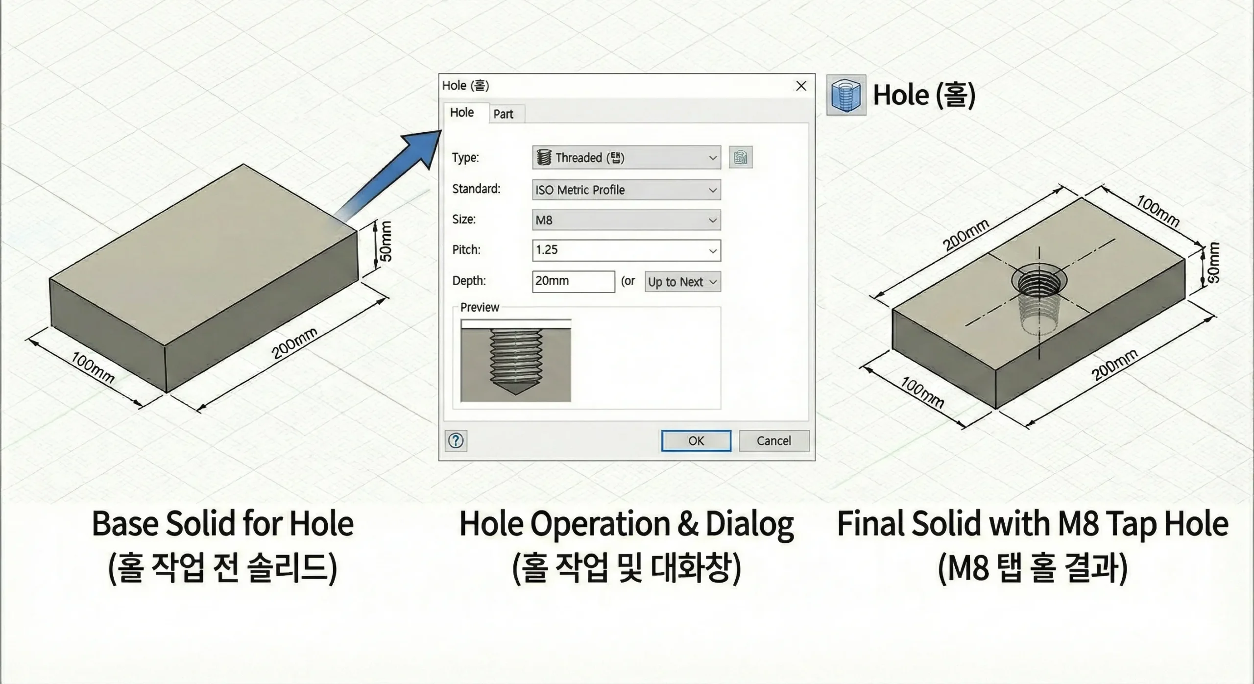
▲ Always use ‘Hole’ for standardized, drawing-ready hole definitions — not Pocket
4. Shaft — The Go-To Tool for Cylindrical Parts
- What it does: Revolves a sketch 360° around a central axis to generate a cylindrical 3D solid.
- Pro Tip: Shaft is essential for modeling locating pins — the key precision component in any jig assembly — as well as any shaft-type parts. Sketch just half the cross-section profile, revolve it, and even a complex stepped pin is done in seconds.
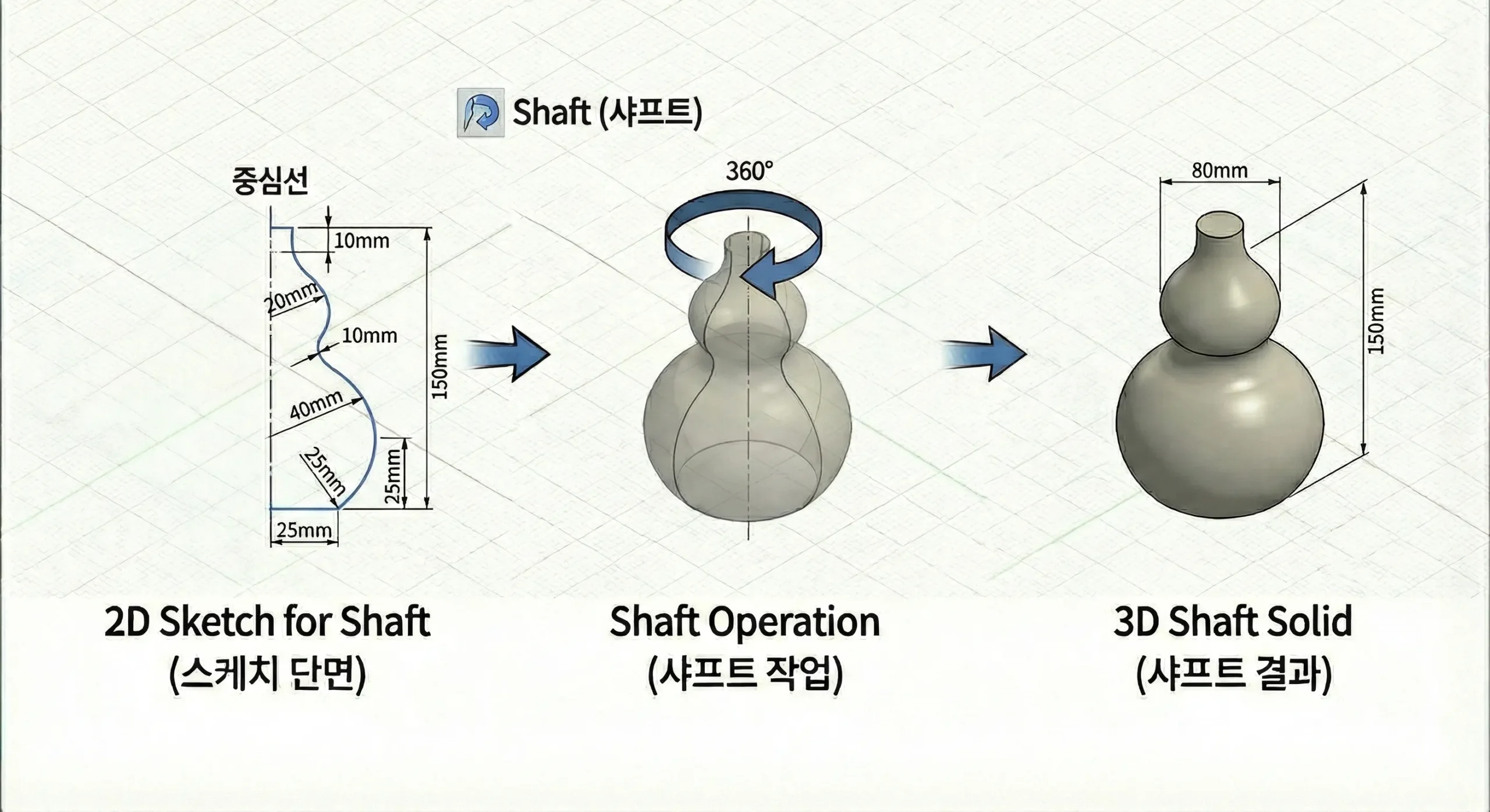
▲ ‘Shaft’ generates precise revolved solids quickly and accurately
5. Edge Fillet & Chamfer — The Finishing Touch for Safety and Machinability
- What it does: Rounds sharp edges (Fillet) or cuts them at an angle (Chamfer) to improve safety and ease of assembly.
- Pro Tip: Apply fillets to exposed outer edges so workers don’t cut themselves during assembly, and add chamfers (typically C1–C2) to insertion points so pins and bolts seat easily. Missing chamfers are the single most common drawing review rejection — don’t overlook them.
In CATIA you can freely set any radius — R1.5, R3.7, whatever you like — with a single click. But real cutting tools (end mills) come in fixed standard sizes. Always choose fillet radii that match commercially available tool sizes when designing. This alone can dramatically reduce machining cost and lead time.
All 5 Features at a Glance
| Feature | What It Does | Primary Use Case |
|---|---|---|
| Pad | Extrude a sketch into a 3D solid | Base plates, bracket frames |
| Remove material from a solid | Clearance spaces, weight reduction | |
| Hole | Create standardized machining holes | Bolt holes, tapped threads, pin holes |
| Shaft | Revolve a sketch around an axis | Locating pins, shaft components |
| Fillet / Chamfer | Round or bevel sharp edges | Safety edges, assembly lead-ins |
Wrapping Up
Master these five commands — Pad, Pocket, Hole, Shaft, Fillet/Chamfer — and you’ll be able to model over 90% of all automotive body jig components without issue.
Rather than chasing flashy surface modeling features, practice combining these five fundamentals to build fast, error-free feature trees. That skill is worth far more on the actual shop floor.