Thinking about opening CATIA and just starting to model in empty space? In automotive body jig design, that’s exactly what you should never do.
“Every single part in an automotive plant shares one invisible coordinate system. That system is called the Carline.”
A modern car is assembled from tens of thousands of components — and every one of them needs to land in exactly the right place. To make that possible, engineers define a virtual 3D grid that runs through the entire vehicle body. That grid is called the Carline, and it serves as the absolute reference coordinate system for everything: design, tooling, welding robots, and final assembly.
1. What Is the Carline?
The Carline is a three-axis coordinate system defined by the vehicle manufacturer and shared across every team and supplier involved in building the car. Think of it as the GPS grid of the vehicle — every point on the body has an address, and that address never changes.
- X-axis (TL — Transverse Line): Runs front to rear along the vehicle’s length. The origin typically sits at the front axle centerline.
- Y-axis (BL — Body Line): Runs left to right across the vehicle’s width. Y = 0 is the exact centerline of the vehicle; positive values go to the right (RH), negative to the left (LH).
- Z-axis (WL — Water Line): Runs bottom to top along the vehicle’s height, measured up from the ground.
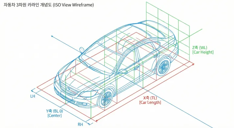
▲ The Carline — a 3D absolute coordinate system that spans the entire vehicle body
2. Why Is the Carline Non-Negotiable in Jig Design?
A jig is, at its core, a fixture that holds sheet metal panels in precisely the right position for welding. And “precisely right” means precisely right in Carline coordinates.
Imagine a designer who ignores the Carline and models a jig starting at an arbitrary origin (0, 0, 0) in CATIA. When that file is merged into a full vehicle assembly simulation, the jig could end up floating in mid-air — or buried underground. The geometry is correct in isolation; it’s just in the completely wrong place in the real world.
The stakes get even higher when you introduce welding robots. Every robot on the production line is taught (programmed) to move to specific Carline coordinates. If the jig design doesn’t align with the Carline from day one, the robot will miss its weld points — and that means scrapped panels, line stoppages, and costly re-teaching.
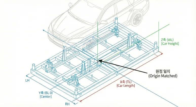
▲ The CATIA model origin correctly matched to the vehicle’s Carline coordinate system
The Carline origin is typically defined at the intersection of the front axle centerline and the vehicle’s longitudinal centerline.
3. How to Apply the Carline in Real Modeling Work
When you receive body panel data from an OEM (Hyundai, Kia, Toyota, etc.), setting up the Carline is the very first thing you do — before placing a single sketch.
- Step 1: Open the reference body data from the OEM and locate the defined X, Y, and Z origin coordinates in the documentation.
- Step 2: When creating the top-level jig assembly (Product) in CATIA, lock the Absolute Axis System to the Carline origin immediately — this is non-negotiable.
- Step 3: When assembling sub-components (locating pins, base plates, clamps), always apply constraints relative to this main Carline axis — never freehand.
Vehicles are bilaterally symmetrical. The Carline’s Y = 0 plane is the vehicle centerline — and that’s a powerful tool once you see it.
- Finish modeling the Left-Hand (LH / driver’s side) jig, then use CATIA’s Mirror feature about the Y = 0 plane to generate the Right-Hand (RH / passenger’s side) jig instantly.
- On drawings, watch the Y-axis sign (+ / −) carefully. A single sign error flips your part to the wrong side of the vehicle — a mistake that’s easy to make and expensive to catch late.
The Three Carline Axes at a Glance
| Axis | Abbreviation | Direction | Key Reference |
|---|---|---|---|
| X | TL (Transverse Line) | Front → Rear (vehicle length) | Front axle centerline = origin |
| Y | BL (Body Line) | Left ↔ Right (vehicle width) | Y = 0 is the vehicle centerline |
| Z | WL (Water Line) | Bottom → Top (vehicle height) | Measured up from ground level |
Wrapping Up
The Carline is far more than a modeling guideline — it’s the shared language that lets designers, shop-floor technicians, and welding robots all work in the same physical space without conflict.
Once you internalize the Carline, you’ll be able to take data from any vehicle program and set up your design reference confidently from the very first click — regardless of how complex the bodywork is.
- X (TL) = vehicle length · Y (BL) = vehicle width (Y = 0 is center) · Z (WL) = vehicle height
- Lock the Absolute Axis System to the Carline before modeling anything — this is the golden rule
- Use the Y = 0 Mirror to generate the opposite-side jig in seconds